News & Information
Membership
Contact Us
Sponsorship
Internet
Cafe
Gallery
People
Project
How to
Links


Electrics
Overview
The electrics of the Sungroper consists of the simple stuff like:
- Dash Board
- Indicator & Brake Lights
- Brake Switches
- Go Relay
- Indicator Control
- 5V Power Supply
- Tachometer
- Direction
- PCB Design
- PCB
Dash Board
The dash board contains the indicator and hazard switches, the motor on switch, the motor speed control and the motor go button and stop light. For the car to operate, the motor switch must be on, and the go button must be pressed to enable the motor. Tapping the brakes turns off the motor which is then reenabled by pressing the go button. (photos)
The dash also contains four digital displays. (photos)
Indicator & Brake Lights
The lights were constructed as a parallel array of strings of LEDs. Each string consists of a current limiting resistor and five high intensity LEDs and when powered from a 12V source produces a lot of light. (photos)
Brake Switches
The Brake Switches consist of normally open (when the brake is released) switches. One side is always 12V, the other side is the return which is then fed directly to the brake lights. This is also used as a signal to disable the motor by generating a short pulse to the Go Relay to turn it off. The driver presses the start button to re-start the motor.
Go Relay
Because the speed control is a dial, it is necessary to have a way to turn off the motor when the brake is pressed. This is accomplished by a static state relay that is turned off by a pulse on the brake peddle and turned on by push button. The relay circuit is designed so that pressing the go button while the brake is depressed has no affect.
Indicator Control
The indicator switches are in parallel with the hazard switch which simply enables both indicators. The indicators use a simple RC circuit to generate the roughly 2Hz signal which enables a ULN 2003 which can handle the roughly 120mA per indicator.
To reduce the maximum current drawn, we use the fact that the indicators are flashing and the fact that no one can see both the front and back at the same time, and so we flash the front and rear indicator out of sync. Thus at any time, only one (or both for hazard) rear indicator or one (or both) front indicators are on. So the mazimum current drain is 240mA for both front or both rear indicators, plus another 240mA for both brake lights. This represents a large part of our 1250mA current available from our 12V supply, even though most of the time none of the lights will be lit.
5V Power Supply
The 5V supply is generated by a TEM2-1211. Unfortunately, this is probably only a little over 50% efficient, so it does not really save much over just using the 12V supply directly through a simple voltage drop regulator.
Tachometer
The motor controller produces a tacho pulse which is basically a 6V pulse version the motor control ground. This is fed to a 6N137 optocoupler because the motor controller runs at battery ground (which is the same as the 24V ground), but the 12V ground is free floating relative to the batteries.
Direction
The motor has a direction input (simply optionally tie one line to ground). The driver has no control over this input, the car is designed only to go forwards, for moving backwards, people push the car. The switch is placed on the circuit board directly in case we need to reverse it for any technical reason.
PCB Design
The design for the PCB was sketched out first, including basic layout and connector pinouts and positions. The design if here.
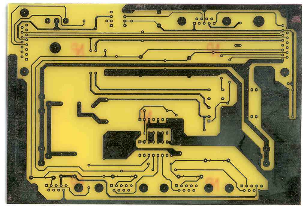
PCB
After prototyping the electrics, we designed a simple PCB which contains all these parts and ten connectors to connect to: front indicator lights (2), rear indicator&brake lights (2), brake switches (2), dash, motor controller, power, and master electronics. The connectors used were either DB9 or DB15 connectors or XLR connectors, because these connectors all have latching mechanisms to ensure nothing comes loose during driving. The PCB was originally roughed out in AppleWorks, and then done in Protel.