
News & Information
Membership
Contact Us
Sponsorship
Internet
Cafe
Gallery
People
Project
How to
Links


Solar Panel Construction
- Overview
- Build the Fibreglass Base Panel
- Drill the Holes
- Mark the Panel
- Place Double Sided Tape
- Tab the Cells
- Stick the Cells
- Wire the Cells
- Seal the Holes
- Spray Conformal Coating
Overview
We decided that for our car we would build panels of solar cells to make them easier to construct and more interchangeable. We did not want to use off the shelf panels because they used lower grade solar cells and were too heavy (consisting of large amounts of glass).
Because our car will be 1.8m wide, and we had a >3m area clear of most obstructions at the back, and the cells are 100*100mm, we decided to initially target the rear area of 17*30 cells. Since 5 and 6 divide 30, and since 6 + 5 + 6 is 17, we decided to make 5*6 cell panels, and tile them across this area (3 panels across the car and five or six panels along the area). Using a 2mm gap between cells and at the edges of the panel, this gives a panel size of 512*614mm. These panels will also be used alongside the drivers cockpit (two on each side) for a total of 20 panels (600 cells). Additional cells will be mounted on the car as space permits.
Each cell has four contact wires (tabs) coming off it, two positive ones on the bottom (about 8.5mm in from the edge) and two negative ones immediately on the edge. These are joined together via fine wires on the cell. Consecutive cells need to be joined positive to negative all the way along the panel. For each cell on the panel, five holes are drilled, one for each contact, plus one "air" hole under the center of the cell which helps to avoid cracking by preventing pressure from building up. The 3mm holes for the positive tabs are drilled 7mm from the edge of the cell, the holes for the negative tabs are drilled 1mm outside the cell edge.
No attempt at "air cooling" was made, although some people recommend cutting a large hole out underneath the center of the cell for this purpose - this was considered too fragile for our needs. Since we did not want any drilled holes directly on the edge of the panel, we arranged them as shown which allowed most of the cells to be easily connected together to the next cell in the circuit, but kept the negative contact points on the edge of the cell away from the edge of the panel.
We learned the techniques we used for building these panels from Stewart Clode of Lake Tuggeranong College, based on how they built their Spirit of Canberra solar car, as well as solar cell soldering techniques from Alain Chuzel and would like to very much thank them for their help and credit them with most of the information (and errors are of course mine!).
The basic idea is to tab the cells, and place the double sided tape on the back of the cells. Then drill small holes in the fibreglass panels, and place the cells onto the panels carefully passing the solar cell tabs through the holes in the fibreglass panel.
Build the Fibreglass Base Panel
The solar panels are constructed on top of composite fibreglass/divinycel foam panels, which have the advantage of being strong, lightweight, and non-conductive.
Instructions on how to build these panels are here.
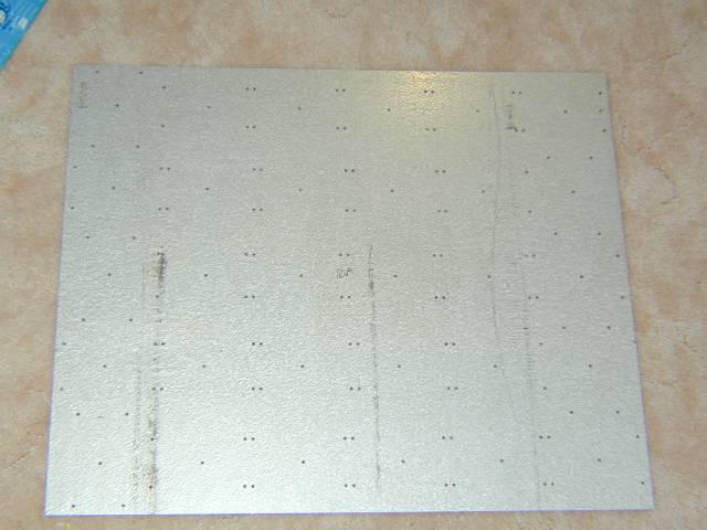
Drill the Holes
Each panel requires drilling 5 holes per cell, which is 150 holes per panel, 3000 holes total. These holes need to be fairly precisely placed (certainly within half a mm), except for the center hole which has a little more freedom.
The first step was to create a template out of metal. Fortunately, Steve Nasso from Pioneer Water Tanks came to our rescue and using a CAD drawing created by team member Bruce Armstrong they punched the template for us on their computer controller punching machine. We had hopes to use the punching machine to punch the panels, but it dented the fibreglass each time it punched a hole. Still, drilling the 150 holes using the template takes only about fifteen minutes, plus another fifteen to thirty minutes cleaning the holes out and removing burrs and such.
Tip: The template should be clearly marked as to which way is up, otherwise your panel will be mirrored - this will still work, but it is better to be consistent. I goofed on this and now all our panels are mirrored from what I initially expected.
Tip: Use a larger drill bit (eg 6-9mm) to deburr the drilled holes.
Tip: Be careful getting fibreglass on your hands, it is itchy stuff!
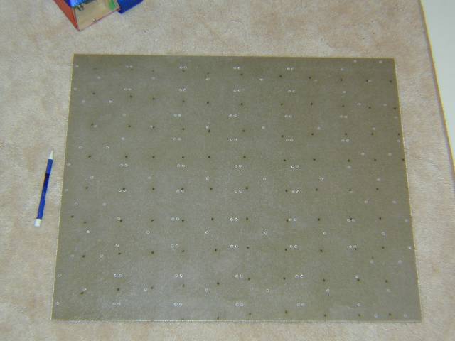
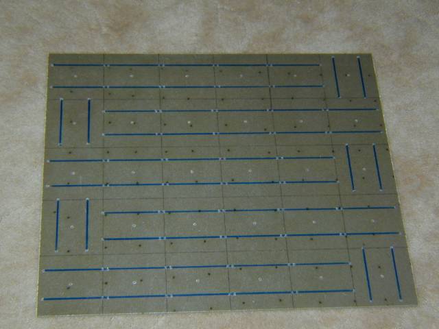
Mark the Panel
After that, the panel needs to be marked with 102mm squares. Center the squares on the center holes drilled (assuming they are accurate) by placing the ruler along the left-most row of center holes with the 51mm mark on the center of the first hole and then marking 0, 102, 204, 306, 408, 510, 612. The 0 and 510 or 612 mark should be about 1mm in from the edge. Repeat on the right-most row and then connect the marks using thin lines. Alternatively, you may be able to line the ruler up based on the negative holes which should be centered on the 102mm squares. Also draw thick lines between the corresponding positive and negative connections so that the tabbing lines for each cell are clearly shown. Marking the panel takes about fifteen minutes.
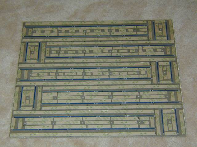
Place Double Sided Tape
Double sided tape is used because it is close to the same thickness as the tabbing on the bottom of the cell - without it, it is very easy to crack the cells when sticking them down (as I did in on cell on my first panel due to excessive solder on the tabbing line). The double sided tape we used is 3M VHB Double Sided Tape Y9473 12mm by 55m roll from Blackwoods (part number 01302224).
Stewart Clode recommends a combination the VHB tape and Sikaflex 227 but we just used the tape (hopefully we will not learn the penalty for ignoring his advice the hard way!).
The important thing is to seal most of the sides so that not too much conformal gets under the cell, to support the cell so that every point is within a cm or so of tape, and to allow air from under the cell to find a path back to the central air hole to avoid any pressure cracking.
The solution we adopted was to place strips of tape parallel to the tabbing so that on strip goes along each side, and then six "half" strips go between the tabbing lines (with gaps in the middle near the air hole). This uses a little less than 50cm of tape per cell.
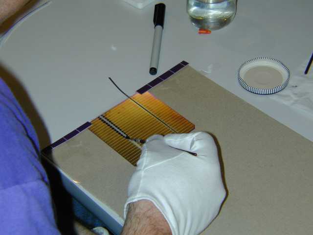
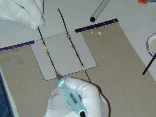
Tab the Cells
Tabbing the cells involves attaching the tabbing ribbon (Tinned Copper Interconnect Ribbon, ETP Copper Strip Annealed Temper, .005 x .080 +/- .003, 60/40 Brookescoat .0004 to .0006 inches from E. Jordan Brookes) to the front and back of the cells. On the front of the cells, Multicore X32-10i flux is painted on to the bus bar, then the tapping wire (cut approximately 30mm longer than the cell) is placed along the bus bar over the flux and a soldering iron with a flat tip (Weller PTCC7 or ETCC is good) at about 700F is run slowly over the tabbing wire. Because no solder is used (just the tinning), it is vital the this is done very carefully and consistently - if it is done badly the tabbing will just peel straight off even though it looks like a perfect job.
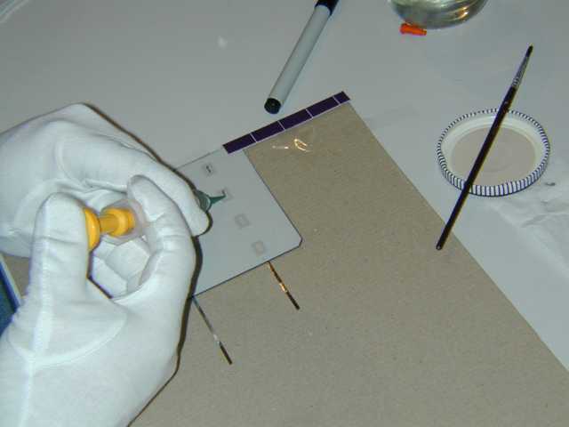
On the rear, place a small amount of solder paste (EFD's Solder Plus Evaluation Kit #62NC-Kit) on each of the connection points. Place the tabbing wire (cut 30mm longer than the length across the connection points) with the wire leading in the opposite direction to the top ribbon and then solder it.
Finally, number the cell and track it so you can see if any systematic problems come up. This is also useful if you will have a "sponsor a solar cell" programme.
This is a very slow process and takes about four to five hours to do 30 cells.
Tip: I stack the cells separated by sheets of A5 paper in stacks of 30 cells.
Tip: Remember to always use disposable cotton gloves while handling the cells to avoid getting oil on them. If you do the job carefully, you may never need to clean the cells (which otherwise is done using acetone but I have never found it to produce as good a finish as the original cells).
Tip: It is strongly recommended that you sacrifice an occasional cell by removing the tabbing wire using a heat gun - run the hot air over the tabbing wire and pull it off as it loosens. Then check the contact made between the cell and the tabbing wire and ensure that there is significant contact (at least as much as the area of the rear tab connections, say 32mm of contact spread evenly over the cell).
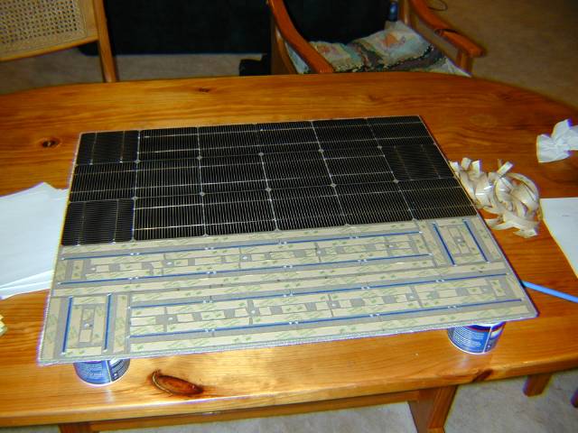
Stick the Cells
Each cell is taken in turn, the tape backing wire is removed, and the tab is bent downwards at 90 degrees (gently and carefully of course!). The ribbon is fed through the matching hole and stuck down with gentle pressure only where the tape is. The board is placed on stands (small drink glasses or art paint cans or such) to raise it off the surface and provide somewhere for the wire to stick out.
Tip: Remove the tape backing for one row at a time.
Tip: Start from the middle row of the board and work towards you to avoid having to work over cells already in place. Turn the board around when you finish the nearest cells and do the other side.
Tip: For each row, insert the cells so that you don't have to feed wires through holes that already have a cell in them - this limits the opportunity to scratch the cells already in place with the tabbing wire.
Wire the Cells
Carefully turn the board over and place it on paper. Then solder each adjoining connection.
I found with the nearby connections, the easiest way was to cut them both to about 10mm of exposed ribbon, bend them both over to the left, then bend the left ones an extra 5mm back over the right one and pinch together with a small pair of pliers.
For the edge connections, take a piece of bussing wire about 16cm long, fold it in the middle at right angles to make an L shape. Cut each ribbon to leave about 10mm exposed and bend them towards the middle of the cell, place the L shape over the four contacts and then bend the last 5mm of each back and pinch them with the pliers. Solder all contacts using standard solder.
Seal the Holes
With the board still face down, you need to seal the holes that the wires go through to prevent rain leaking through. We used 5-minute epoxy (Araldite) because it dried quickly (so the panels could be put away), because it presumably bonds well to the fibreglass epoxy, and because it is fairly thick and so wont just run down into the holes.
DO NOT SEAL THE CENTRAL AIR HOLES! These holes are there to avoid any pressure buildup under the cell when it heats, we carefully drilled these holes and laid the tape to ensure air paths all over the bottom of the cell, it would be a shame to seal them now! If later testing determines that water can leak through the air holes, then it is presumably ok to seal them since the air must have a path from the air hole to the outside - for now we are just going to leave them open and see whether it is a problem or not.
Spray Conformal Coating
Use Dow 1-2577 Conformal (from Australian Isola Materials), about 3 of the glass 'quart' bottles for 8 square meters. The instructions for spraying say to use Toluene (or Toluol) - such as Wattyl's T2 thinners, but this does not work well. Others say naptha, but that may be hard to get in Australia. We used acrylic lacquer thinners (Wattyl AP 504), about 1.5 parts Conformal to 1 part thinner (or 20% thinner by volume, thinned basically so it goes through the spray gun). Put on three very thin dry coats. Conformal requires a fair bit of expertise to spray successfully, so we used a professional spray painter (Aeropaint). Conformal is very nasty stuff - always wear a respirator.
If the coating goes badly, put on Ansell rubber gloves, get a respirator (organics solvent rated cannister) and a few clean cotton rags. You carfeully tip some AP 504 thinners on the conformal and it dissolves. You carefully wipe all the conformal off. Repeatedly clean the surface with new rags a couple of times, let it dry then have another go spraying.